
Beamline 7.2W
Macromolecular Crystallography
Beamline Layout and Specification
BL7.2W Optical Layout
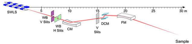
Figure 1 Simplified schematic of BL7.2W from source to sample.

Figure 2 Detailed schematic of BL7.2W showing component positions and distances.
The major beamline components include a cylindrical collimating mirror (CM), a double-crystal monochromator (DCM), and a toroidal focusing mirror (FM), as shown in Figures 1 and 2. CM, a collimating mirror, collimates the white beam from the front-end as the distance from the source is 9700 mm. CM is a cylindrical mirror (R = 5,542,870 mm) coated with Rh/Pt. The grazing angle is adjusted to be 3.5 mrad. FM is a focusing element, thus placing to allow the surface of the mirror facing down to the floor. The distance from the source to FM is 20,000 mm. The sample position is focused on the existing hutch, and is chosen to be at 30,000 mm from the source. FM is a toroidal mirror (R = 5,714,297 mm and r = 46.7 mm). From the meridional and sagittal focusing term, the angle of incidence is found to be 89.799° or equivalent to the grazing angle of 3.5 mrad. Commercial DCM from Kohzu; model TSR-2DCM, thus adopting two cam stages for the main theta axis movement to maintain a fixed-exit beam.
👉 More information about the beamline specification has been published:
Songsiriritthigul, C. et al. (2023). Performance of micro-beam X-ray absorption spectroscopy at beamline 7.2W of Synchrotron Light Research Institute. Radiation Physics and Chemistry.
DOI: 10.1016/j.radphyschem.2023.110768
BL7.2W Specification
Source Type
6.5-Tesla Superconducting Wavelength Shifter (SWLS)
Photon Energy
4.0–22.7 keV (3.10-0.55 Å)
Optic
Cylindrical Collimating Mirror (Rh/Pt coated)
Fixed Exit Double Crystal Si(111) Monochromator
Toroidal Focusing Mirror (Rh/Pt coated)
Polycapillary lens
Photon Flux
1.40 x 10¹¹ phs/s/100mA @10 keV at XAS/XRF station
5.30 x 10⁹ phs/s/100mA @13.035 keV at TXRF station
1.57 x 10⁸ phs/s/100mA @10 keV at micro-XAS/XRF station
Beam size
3 mm (H) x 2 mm (V) at XAS station
4.2 mm (H) x 2 mm (V) at XRF station
3 mm (W) x 20 µm (D) of typical beam size for TXRF station
20 µm for micro-XAS/XRF station @12 keV
Beam Divergence
0.27 mrad (H) x 0.04 mrad (V)